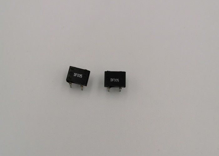
1.0 A Voltage 50-1000V Diode Bridge Rectifier DF01 DF02 DF04 DF06 DF08 DF10
FEATURES
♦ Plastic package has Underwriters Laboratory Flammability Classification 94V-0
♦ This series is UL recognized under Component Index, file number E54214
♦ Glass passivated chip junctions
♦ High surge overload rating-50 amperes peak
♦ Ideal for printed circuit boards
♦ High temperature soldering guaranteed: 260°C/10 seconds at 5 lbs. (2.3kg) tension
MECHANICAL DATA
Case: Molded plastic
Terminals: Plated leads solderable per MIL-STD-202,
Method 208
Mounting Position: Any
Weight: 0.04 ounce, 1.0 grams (approx)
Polarity: Marked on body
Typical Applications:
General purpose use in ac-to-dc bridge full wave rectification for SMPS, lighting ballaster, adapter,
battery charger, home applicances, office equipment and telecommunication applications.
Maximum Ratings & Thermal Characteristics
Rating at 25 C ambient temperature unless otherwise specified, Resistive or Inductive oad, 60 Hz.
For Capacitive load derate current by 20%.
| Parameter |
Symbol |
DF005S |
DF01S |
DF02S |
DF04S |
DF06S |
DF08S |
DF10S |
UNITS |
| Maximum repetitive peak reverse voltage |
VRRM |
50 |
100 |
200 |
400 |
600 |
800 |
1000 |
V |
| Maximum RMS bridge input Voltage |
VRMS |
35 |
70 |
140 |
280 |
420 |
560 |
700 |
V |
| Maximum DC Blocking Voltage |
VDC |
50 |
100 |
200 |
400 |
600 |
800 |
1000 |
V |
|
Maximum instantaneous forward voltage drop
per leg at 1.0A
|
VF |
1.1 |
V |
|
Maximum DC reverse current at rated TA =25 C
DC blocking voltage per element TA =125 C
|
IR |
10
500
|
μA |
|
Maximum average forward rectified
output current at TA=40 C
|
IF(AV) |
1.0 |
A |
|
Peak Forward Surge Current, 8.3 ms single half sine-wave
superimposed on rated load (JEDEC method)
|
IFSM |
50 |
A |
| Rating for fusing ( t<8.3ms) |
I 2 t |
10 |
A2sec |
| Typical thermal resistance per element (1) |
ReJA |
110 |
℃/W |
| Typical junction capacitance per element (2) |
Cj |
25 |
pF |
|
Operating junction and storage temperature
range
|
TJ,
TSTG
|
-55--150 |
℃ |
Notes: (1)Thermal resistance from Junction to Ambemt on P.C.board mounting.
(2)Measured at 2.0MHz and applied reverse voltage of 4.0 volts.
Size:

Why choose us?
1. ISO9001:2008 certified factory
2. 20 years rich experience in the diode production
3. Strict quality control, achieve customer's maximum satisfaction
4. The Annual production capacity is over 2 billion
 Your message must be between 20-3,000 characters!